Installing ZX8-CCB in the RF modulator housing
- Before you start, I highly recommend that you verify that your computer's video output is working so you don't attribute problems that have another origin to your adaptor installation. Two possible ways to do this are:
- If you can see a display on your computer TV, no matter how noisy and poorly formed and you can see it change when you restart your TS1000 and then press the P key for print, then you are good to go.
- If you can't do the above, but you have an oscilloscope, I would recommend that just after you remove the bottom half of the TS1000 case, you test to see you are getting a composite video output waveform similar to the one shown here in figure xx from pin 16 of the ULA chip. Be careful not to short adjacent IC pins.
- Open the bottom half the TS1000 clamshell case
- Set the TS1000 upside down on a table
- Remove 3 rubber feet and store saftely
The following 2 steps require a small philips head screwdriver. I find size #1 is perfect. - Remove 3 black screws and store safely
- Remove the bottom half of TS1000 case.
- Remove the TS1000 printed circuit board from the top half of the clamshell case.
- remove the two silver screws
- THE MOST DANGEROUS STEP - very gently and carefully leaving the top half of the case on the table, rotate the printed circuit board 180 degrees
- do not hit the case support posts - you can break them
- do not pull at all on the membrane keyboard flexible cable
- Gently grip one of the keyboard membrane's flexibles connectors with your fingers, as close to the PCB connector and remove the cable from the connector
- Similarly remove the second flexible cable in similar fashion and set the top half of the case with the keyboard aside
- Preparing the RF Modulator
- Remove the modulator form the TS1000 PCB
- cut the wire that go from the RF modulator from the TS1000 printed circuit boar
- remove the top of the RF modulator - a small screwdriver may help pry it off
- turn the TS1000 printed circuit board upside down on your work surface. Be carefull not to damage or bend any components
- each of the two short sides of the RF Modulator has a mounting prong protruding through a hole int the TS1000 printed circuit board and solder.
- With a soldering iron and solder sucker, or a professional vaccum pump desoldering tool, remove what solder you can from both of the modulator prongs.
- Then without damaging any components elsewhere on the TS1000 PCB, melt the solder on the prong nearest the edge of the PCB and when the solder is molten pry the end of the RF modulator out of the hole in the PCB with a large flat screwdriver.
- Then heat the prong on the other end and remove the modulator from the TS1000 PCB
- Remove the RF Modulator board from the RF Modulator housing
- with a pair of wire snippers or side cutters cut the components connecting the modulator board form the RCA Video jack.
- with a pair of wire snippers of side cutters cut and remove the nylon insert from the 3 holes on the modulator and discard it. The hookup wires we will be using is insulated, and it will be easier to pass the wires thru the larger remaining holes.
- remove the bottom lid of the RF modulator ( you may need a screw driver ) and set it aside.
NOTE: The top and bottom lids of the RF modulator are not the same. They are more like mirror images of one another as far as the locationof the circular notch in them that clears the Video jack. - The RF Modulator board is soldered to the RF modulator housing with four large solder connections. WARNING: Be careful in this next step not to burn yourself. The RF modulator housing will get hot. With a heavy duty soldering iron and solder sucker, or a good vacuum pump solder remover, remove as much of the four solder connections as you can. Then using some combination of handtools remove the RF modulator board. The RF modulator board is surprising strong, but I do find I can break and cut it with a combination of sharp wire cutters and screwdrivers. You can even use a power tools like a drill or moto-tool if you prefer, as long as you are carefull.
- Once you get the modulator PCB out, you can use a soldering iron and solder sucker to cleanly remove the solder and any connected component parts from the video jack.
- This is a good time to remove any stubs of the three wires that you cut that went from the TS1000 PCB into the modulator. Note that those wire carried Ground, 5V Power, and some form of video signal, bepending on computer model ( US CH2-3 or European VHF 33). I recommend you use the Ground and 5V Power pad locational for your ZX8-CCB hookup. Therefore remove any stubs
- Resolder the the RF Modulator onto the TS1000 PCB
- remove the solder as best you can from the two holes on the PCB that mount the modulator
- insert the modulator in the two holes and try and get the modulator housing flush to the PCB
- solder the two modulator prongs to the TS1000 PCB
- Remove the modulator form the TS1000 PCB
- Preparing the ZX8-CCB and inserting it into the RF modulator housing
- This is the time to make sure you understand where on the TS1000 you will be connecting the wires from ZX8-CCB.
[ This is also a step where you have more one location that you can pick up each necessary input signal, and even different choices depending upon whether you have a CH 2-3 VHF modulator (Mostly the United States ) vs a CH33 UHF modulator (Mostly Europe]. - There are five connections to the ZX8-CCB.
- 3 inputs: 5V Power, Ground, and the composite video signal from the ULA chip
- 2 outputs: Ground and the reformed composite video for output
- You can hook up the connections in any sequence, and the color of the wires you use does not matter, but I suggest the following order and wire colors:
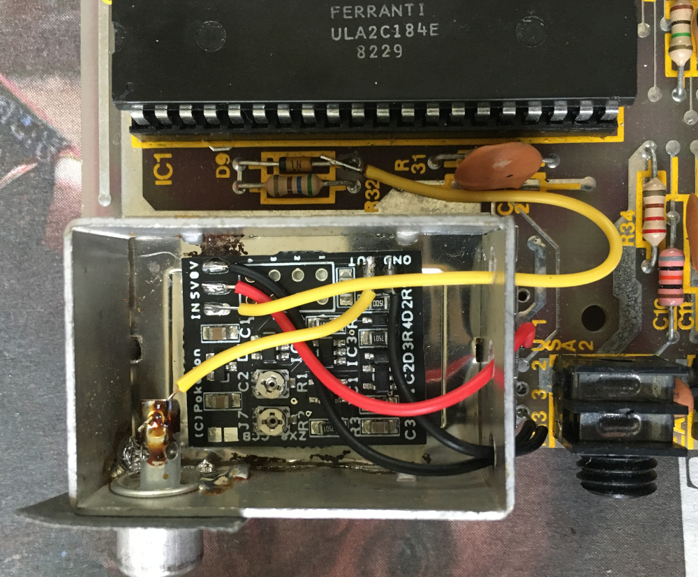
- There are two ways you can orient the ZX8-CCB in the modulator housing and both work well. If you orient plan on orienting your board as in Figure 2, I suggest you cut the following lenghts or wire, strip and tin one end of the wire. Melt a small amount of solder on each of the ZX8-CCB's 3 input and 5 output pads.
- OPTIONAL: The standard video for a TS1000 is black characters on a white screen. I you know you want white characters on a black screen ( inverted video ) you can short the two pads on the ZX8-CCB that do this. Personally, I have never tried it.
- Prepare 5 wires with the following lenghts by stripping and tinnning one end leaving about 3 mm bare ( uninsulated ), and solder them to the ZX8-CCB in the orientation shown in Figure 3.
- Cut a length of double-sided sticky tape and press it onto the bottom of the ZX8-CCB.
- HOOK UP THE 2 GROUNDS
- I like to follow the convention and use black wire for my grounds. There are two ground pads provided on the ZX8-CCB. Feed both wires through the Modulator case hole nearest the edge of the TS1000 PCB. Cut them to the appropriate length to connect to the ground hole in the PCB. Then twist them together and tin their ends. Put them in the PCB hole and solder them.
- Next I am going to connect the yellow video output wire to the video jack. I like to cut the wire to length, strip and tin the end, hook it through the hole in the jack center post and solder it.
- Red is the convention for power connections. I'll take the red wire cut it to length, strip and tin the end, insert it in the correct PCB hole and solder it.
- The last connection is perhaps the trickiest. The composite video signal from the ULA's pin 16 is what we want to connect to. On the TS1000s and US CH 2-3 ZX81s that signal connects to a diode in series with a resistor before ethe signal passes into the RF modulator. I like the ZX8-CCB's yellow video input wire through this hole in the modulator case, the one fartest from the edge of the PCB. I strip and tin the edge and just tack it to the anode side of the diode being careful not to overheat the diode. That completes all the ZX8-CCB wiring.
- You don't want to put the lid on the RF Modulator yet, because we may have to adjust one of both potentiometers on the ZX8-CCB to get a good video signal on our computer.
- This is the time to make sure you understand where on the TS1000 you will be connecting the wires from ZX8-CCB.
- Testing and adjusting
- make sure your TS1000 board has nothing under it but a non-conductive flat surface. Connect the video cable between your modulator's video jack and the composite input of your TV. General the composite inputs to your TV have 3 color coded and labeled RCA type jacks, Left and Right audio being white and red respectively, and the yellow video jack, which it the one you want, is yellow.
- Then connect the 9VDC power supply to your computer power jack. It's the jack fathest from the modulator.
- Set your TV to composite input. If you are lucky you will see the K displayed in the lower left of your screen. It is also common to nothing, or just a short black bar at the bottom of your screen. Be gentle and don't break the potientiometers. With a 2mm or narrower flat head screw driver gently adjust the potentiaomters to get a clear letter K on your screen. It is important to understand that the potiometers do not rotate 360 degress. they only travel about 240 degrees.
- MORE NOTES ON ADJUSTING POTS IS NEEDED
- TROUBLE SHOOTING. If you don't see a video signal, and you have an oscillocope, I would recommend checking first that there still is a composite video signal on PIN 16 of the ULA.
- Adjust the pots for best image
- replace the lid on the RF modulator housing, pressing it down firmly
- disconnect the power and video cables from your computer and gently and carefully turn the TS1000 PCB over.
- carefully reconnect the keyboard membrane to the two sockets in the TS1000 PCB. I find it's is very easy to bend the flexible cable and tear them. I like to find thin piece of clear plast from a blister-packed consumer item, cut it the same width as a flex cable and use it as a stiffener. I hold it and the flex connector against one another and insert the flex cable into the connector. Then I carefully slip out the clear plastic stiffener.
- Repeat this for the second flex cable. You need good eyes to make sure the conductive traces on the flex cable are aligned with the conductors on the flex cable connectorson the TS1000 PCB.
- Carefully rotate the case top without snagging and breaking the plastic PCB support posts on the case, or tearing the keyboard flex cables.
- Align the PCB on the posts and attech it with the 2 silver screws. Do not overly tightesn or you will bread the plastic posts.
- turn things over and attach the bottom of the TS1000 case with the 3 black screws. Replace the 3 rubber feet.
- reconnect your cables and start enjoying your new video output.